


News Details
-
Cast iron platform/flat plate series
-
Machine Tool Casting Series
-
3D Flexible Welding Platform Series
-
Granite and Marble Series
-
Ground rail groove rail series
-
Cast iron bending plate series
-
Square Box and Square Tube Series
-
Machine tool pad iron series
-
V-shaped frame series
-
Square ruler series
-
Skewner series
-
Magnesium aluminum alloy series
-
3D Platform Fixture Series
-
Ring gauge series
Usage method of locking pin for 3D platform
Date: 2021-05-04 19:04:16 Views: 78
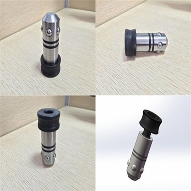
Locking tool, main material 45 # adopts layer by layer quenching method. Locking pin is a cylindrical pin that achieves axial locking or loosening between modules and modules, modules and platforms by rotating the screw head or handle.
Product: Main components: locking body, locking rod, steel ball (or handle), different structural forms and other different components.
Product classification: Standard locking pin, countersunk locking pin, handle type locking pin
There is a locking rod inside the locking body, and the lower part of the locking rod is a circular table body. The upper part of the locking rod is a handle head with an inner hexagonal hole. The circular table body contacts the steel ball placed in the circular hole of the locking body. The upper end of the locking rod extends out of the locking body and is connected to the internal thread of the locking body through the external thread in the middle of the locking rod. By rotating the handle of the locking rod head, the steel ball placed in the hole of the locking body is squeezed, diffused or retracted by the circular table body at the bottom of the locking rod, causing the steel ball to protrude or retract from the outer surface of the locking body, thereby achieving the function of locking the workpiece. The locking pin has the advantages of easy locking, positioning, and disassembly.
Usage: The locking pin body is equipped with 5 concentric steel balls. When the locking pin thread is loosened, the steel ball will automatically retract into the locking body. At this time, the locking pin can be inserted or withdrawn into the circular hole of the locked workpiece. When in use, insert the locking pin into the hole of the locked workpiece and gradually tighten the head of the locking pin by hand, while the steel ball gradually protrudes. The locking pin automatically aligns and clamps the module, and then tighten it with a wrench. The tightening force should be appropriate and not too large (usually the wrench can be rotated by 45-60 °). After tightening the locking pin, it can achieve a clamping force of 50kN and a shear force of 250kN. At the same time, various lengths and countersunk locking pins are designed according to different usage scenarios.
 Recommended Products
 CONTACT
—— Hotline:15733755098
—— Email:826899931@qq.com
—— Whatsapp:0317-8335666
—— Address:Xinhua Street, Jiaohe Town, Botou City